Romana Networking
This document explains some of Romana’s core networking concepts. Oftentimes, a detailed understanding of those is not required, since Romana strives to provide sensible defaults and working out-of-the-box configurations. But for custom deployments or advanced configuration, having an understanding of those concepts is helpful.
Terminology
The following terminology is used throughout this document:
agent: This is a Romana component, which runs on every node in a cluster. This agent is used to configure interfaces, routing or network policies on that host.
CIDR: ‘Classless Inter-Domain
Routing’. We use the term CIDR to refer specifically to the ‘CIDR
notation’, which is a compact representation of an IP address and
routing prefix. Most commonly, however, we use this notation to describe
ranges of addresses. For example, the CIDR of 10.1.0.0/16 describes
all IP addresses from 10.1.0.0 to 10.1.255.255.
Clos Network: A Clos network is a structured, hierarchical network topology often used for data center networks. It can be described as a tree-like ‘spine and leaf’ architecture, with racks of servers as the bottom layer. Those servers are typically connected to a ToR (‘top of rack’) switch or router, which represents the next layer. An entire rack (servers plus ToR) may be considered a ‘leaf’ in this architecture. Core routers or switches are then used to connect those ToRs, often in a highly redundant manner, which can tolerate failure of core devices. Those core devices then form the ‘spine’ in the architecture. This is a simplified description and countless variations of Clos networks exist. For example, additional layers may be inserted. Or in various large core networks, and entire spine may be considered the ‘leaf’, depending on the scope of the discussion and network. Connections between spines and leafs may be managed by vendor specific network fabric implementation, and so on.
endpoint: Romana deals with the provisioning of networking for workloads in clusters (VMs for OpenStack, pods for Kubernetes). Due to a network-centric view, for Romana the most important aspect of a workload is the ‘network endpoint’, which is the IP address and network interface of the workload.
host: In this context, usually a server computer that is part of a cluster, such as OpenStack or Kubernetes. In this document we use the term ‘host’ or ‘node’ interchangeably.
IPAM: ‘IP Address Manager’. A service that manages IP addresses in a network. If anyone in the network needs a new address, a request can be sent to IPAM to get the ‘next’ available IP address from some pre configured range. Romana’s IPAM is an extremely important component since carefully chosen addresses and network prefixes are used to greatly collapse routes and reduces the impact of route distribution on hosts and networking equipment.
master node: One of the nodes of an OpenStack or Kubernetes cluster, which fulfills ‘master’ or ‘controller’ functions. This is typically where central components of the cluster infrastructure run. Workloads (VMs or pods) may or may not run on master nodes, depending on configuration.
node: A host that is a member of a cluster (either OpenStack or Kubernetes). In this document we use the term ‘host’ and ‘node’ interchangeably.
policy: Romana provides network policies to manage network traffic and allow or deny access. You can always use the Romana CLI and API to define policies. For Kubernetes clusters, Romana also implements a direct and automatic mapping of Kubernetes policies to Romana policies.
route aggregation: Since all endpoint IP
addresses are fully routable, Romana needs to configure and manage the
routes within the network. Great emphasis has been placed on collapsing
those routes (aggregation), so that only very few routes
actually need to be configured and maintained within the network infrastructure. For example, if there are two routes to
adjacent CIDRs 10.1.0.0/25 and 10.1.0.128/25,
which point to the same target then this can be collapsed into a single
route for the CIDR 10.1.0.0/24. Romana facilitates a special
IPAM that is aware of network topology in order to
assign IP addresses to endpoints in a manner that makes it easy to
automatically aggregate routes.
network topology: A network topology describes the layout of elements in a network. How are hosts, switches and routers connected? How can two components communicate? Who can reach whom directly and who needs to forward packets on behalf of others? Traditional network topologies are ‘bus’, ‘star’, ‘ring’ or ‘mesh’. In modern data centers topologies can be complex and may contain some mixture of those types, often adding certain tree-like hierarchical aspects to the topology, for example in Clos networks.
workload: In OpenStack clusters this is typically a VM, while in Kubernetes clusters this is normally a pod. These workloads run on the cluster hosts. Each workload is represented by a network endpoint, consisting of a network interface that is configured on the host as well as an assigned IP address.
Networking
Fully routed networks without overlays
Romana does not use network overlays or tunnels. Instead, endpoints (VMs for OpenStack, pods for Kubernetes) get real, routable IP addresses, which are configured on cluster hosts. To ensure connectivity between endpoints, Romana manages routes on cluster hosts as well as network equipment or in the cloud infrastructure, as needed.
Using real, routable IP addresses has multiple advantages:
- Performance: Traffic is forwarded and processed by hosts and network equipment at full speed, no cycles are spent encapsulating packets.
- Scalability: Native, routed IP networking offers tremendous scalability, as demonstrated by the Internet itself. Romana’s use of routed IP addressing for endpoints means that no time, CPU or memory intensive tunnels or other encapsulation needs to be managed or maintained and that network equipment can run at optimal efficiency.
- Visibility: Packet traces show the real IP addresses, allowing for easier trouble shooting and traffic management.
Romana address blocks
To increase scalability and reduce resource requirements, Romana
allocates endpoint addresses not individually, but
in blocks of addresses. Each block can be expressed in the form of a
CIDR. For example, a typical address block may have 4
bits (a /28 CIDR), and therefore could contain up to 16 different IP
addresses. Routing is managed based on those
blocks. Only one network route is required for all addresses within this
block. Therefore, address blocks are an important contribution to route
aggregation.
Let’s look at an example to illustrate:
Assume Romana has been configured to use addresses out of the
10.1.0.0/16 address range and to use /28 blocks. Now assume a
first workload needs to be started. The cluster scheduler decided to
place this workload on host A of the cluster.
Romana’s IPAM realizes that no block is in use yet on host A, allocates
a block and ‘assigns’ it to host A. For example, it may choose to use
block 10.1.9.16/28. As this assignment is made, the Romana agent on
the cluster hosts may create routes to this
block’s address range, which point at host A. The address 10.1.9.17
(contained in that address block) could be chosen by IPAM and is
returned as the result of the original address request. Therefore, the
first endpoint gets address 10.1.9.17.
Now a second endpoint needs to be brought up. The scheduler chose host
B. IPAM finds that no block is present on host B yet, chooses one (maybe
10.1.9.32/28) and returns an IP address from that block. For example
10.1.9.33.
The two endpoints (10.1.9.17 on host A and 10.1.9.33 on host B)
can communicate with each other, because Romana automatically setup
routing for those address blocks.
If now a third endpoint needs to be brought up, and it is again
scheduled to host A, then IPAM detects that there is an address block
already on host A, but it is not fully used, yet. Therefore, it returns
a free address from that block, for example 10.1.9.18. Importantly,
no new block allocation was necessary in that case, an no additional
routes had to be configured. This image illustrates the state at this
point:
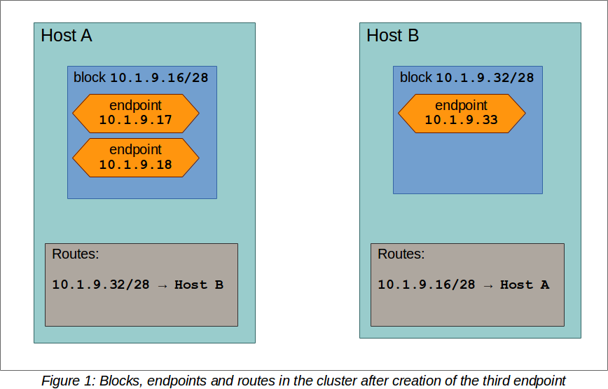
State in a the cluster after third endpoint was created
As a result, the need to update routes on hosts or in the network infrastructure is greatly reduced. The larger the address blocks, the less often routes have to be configured or updated.
Choosing the right address block size is a tradeoff between the number of routes on one hand, as well as potentially wasted IP addresses on the other: If the block size was chosen too large then some IP addresses may never be used. For example, imagine a block size of /24. The block may contain up to 256 addresses. If on a particular host you never run that many workloads then some of those addresses may be wasted, since they are not available on other hosts.
If a block size is chosen too small then for a cluster with many endpoints Romana has to create a lot of routes (either on the hosts or the network equipment). Romana provides many features to reduce the number of routes and route updates in the network and therefore - for most cases - we recommend address block sizes of at least 4 or 5 bits.
An address block, while in use, is tied to a specific host. When workloads are stopped and the last address within a block is released, the block itself goes back into Romana IPAM’s free pool. When it is used the next time, it may be allocated to a different host.
Route management
Depending on the network’s topology Romana creates and manages routes for address blocks by a number of different means.
In most cases, the Romana agents on the cluster hosts create routes to address blocks on other cluster hosts, at least for those hosts that are on the same L2 segment. This is often the case if the ToR acts as a switch for the hosts in the rack and is sometimes described as ‘L2-to-host’. The following image illustrates this network configuration:
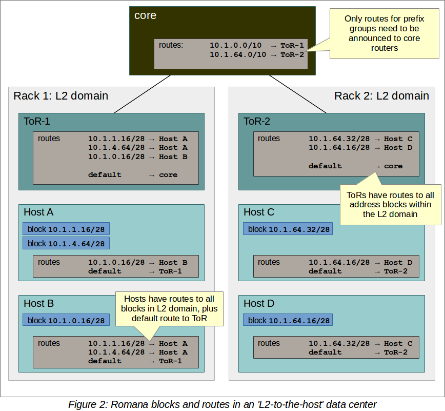
Routes in an L2-to-host data center
Some networks are designed for ‘L3-to-host’, meaning that hosts do not share an L2 segment. In this case, no routes need to be configured on the hosts at all. Routes to address blocks are installed on the ToR instead. Traffic will simply use the default route to the ToR switch where it will forward to the propher endpoint. The following image shows where routes are created in an L3-to-host configuration:
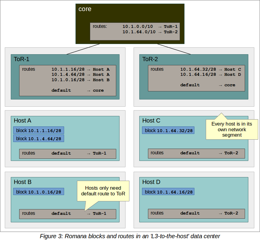
Routes in an L3-to-host data center
Routes can be advertized to the ToR using either BGP or OSPF route distribution protocols.
Romana is provided with topological information about the network in which it is deployed as a configuration parameter. It then uses this information to maintain aggregated routes <#term_aggregation>`__ which reduces the number of routes that need to be created and updated. In many cases all endpoints can be reachable with very small numbers of routes and few, if any, route updates required.
Topology
Prefix groups
Prefix groups are one of the key ideas behind Romana’s IPAM. With this concept, IP addresses for endpoints are chosen from the same CIDR if they are created in ‘close proximity’.
For example, assume you run a cluster in a data center network, consisting of multiple racks full of servers. Romana IPAM may consider all the hosts within a rack to be part of the same prefix group. This means that all address blocks - and therefore all endpoint IP addresses - assigned to those hosts will share the same address prefix. This then means that the ToRs (top of rack) switches in the data center only need to know a single route to be able to send traffic to all the endpoints within a rack: With this topology aware IPAM, Romana is able to drastically collapse the routing table, reducing the memory requirements, CPU load and network load of the network infrastructure.
Prefix groups also allows more specific route filtering between routers which can prevent route injection attacks.
Let’s look at an example in more detail.
Assume your data center consists of four racks. Each rack has a ToR leaf, connected to a pair of spine core routers.
Assume further that the overall address range for Romana is
10.1.0.0/16.
These four racks are specified in a topology
map: a configuration that describes the network
topology and which is provided to Romana as input.
Romana then takes this information and automatically carves up the
overall CIDR available into four sub-ranges:
10.1.0.0/18, 10.1.64.0/18, 10.1.128.0/18 and
10.1.192.0/18. It then assigns these sub-ranges as a prefix groups to the ToR and organizes the hosts in each rack to get addresses from within the prefix group. For example, 10.1.0.0/18 may be assigned to rack 1, 10.1.64.0/18 to rack 2, and so on.
Then, if the cluster scheduler wishes to bring up a workload on any host
in rack 1, Romana IPAM will make sure that the address block used for
this endpoint will be fully contained in the 10.1.0.0/18 CIDR. For
example, the address block may have the CIDR 10.1.0.8/28.
Likewise, if an address block is needed on any host in rack 2, it will
have a CIDR that’s contained within the second prefix group’s CIDR. For
example, 10.1.64.8/28.
As a result, to send outgoing packets to endpoints in other racks, the spine routers only need to have four routes: One route for each prefix-group’s CIDR to the ToR for that prefix-group / rack. These routes do not even require updating.
Note that every environment is different. Romana provides for a great deal of flexibility to organize hosts into prefix groups and how to configure the announcement of routes. Prefix groups are not only important in data centers, but also in clusters that are running on cloud infrastructure. Where and how routes are announced and created may differ depending on the environment. Romana supports a number of options.
Topology map
A topology map is one of the configuration parameters for Romana and is the basis on which Romana IPAM calculates CIDRs for prefix groups. The topology map is a representation of certain aspects of the actual network topology.
Here are a few simplified examples:
Example 1: Flat network, single prefix group
In this example, any host that is added to the cluster will be automatically assigned to the single prefix group we have defined here.
{
    ...
    "map" : [
        {
            "name"   : "all-hosts",
            "groups" : []
        }
    ]
    ...
}
The CIDR of the prefix groups will be the entire CIDR given to Romana to work with.
Example 2: Data center with four racks
Here, we define a topology with four prefix group, one for each rack in our data center.
Note the ‘assignment’ specifier. This matches any tags assigned to cluster hosts. Therefore, as cluster nodes are added, the operator should ensure that tags with those values are specified for each host. Both OpenStack as well as Kubernetes offer the option to tag hosts as they are added to the cluster. In some cloud environments, hosts are automatically added with a region or zone identifier, which can then be used in the same manner.
{
    ...
    "map" : [
        {
            "name"       : "rack-1",
            "assignment" : { "my-location-tag" : "rack-1" },
            "groups"     : []
        },
        {
            "name"       : "rack-2",
            "assignment" : { "my-location-tag" : "rack-2" },
            "groups"     : []
        },
        {
            "name"       : "rack-3",
            "assignment" : { "my-location-tag" : "rack-3" },
            "groups"     : []
        },
        {
            "name"       : "rack-4",
            "assignment" : { "my-location-tag" : "rack-4" },
            "groups"     : []
        },
    ]
    ...
}
In this example, Romana’s entire address range is automatically split into four CIDRs and each of those CIDRs is assigned to one prefix group. This means that all endpoints in a given rack will share the same address prefix, which allows for the complete aggregation of all routes for the endpoints in that rack.
More comples examples for a number of real world topology maps are available in Custom Topologies section of ‘Advanced Topics’